Maker Space

This page details stuff I have made.
I have been making devices & systems since my early teens. Initially making sound systems because I couldn’t afford hi-fi and loved music. As I became more interested in music I was driven to explore electronics and engineering. I was an early explorer of electronic music and home recording. Back in the day, I scavenged bits of radios and other gadgets from dumps and also bought bits from Peats. It was this interest in making audio gear that led me to choose to study electronic engineering in Kevin Street. You will see a strong music technology trend in the maker projects below.
Being able to make devices has proved to be a valued skill in the hospital setting. In fact I think this is what got me into the health service in the first place. You will see many projects that detail devices built to solve practical needs in the health service or to support research projects I was associated with.
Today I work using technology in both the music/creative space and also in the healthcare space. The engineering is common to both spaces. Often ideas or concepts from the music technology world would inspire creative solutions in the health space and vice versa.
I don’t associate myself closely with the “Maker” subculture. Yet another label to negotiate! However, I do like the value it places on individuals taking control of technology to build solutions or adapt devices and environments to their own needs. It feels that the projects detailed here could be better described as “creative engineering” or even “engineering as art”. Perhaps all this activity happens in an interdisciplinary space where engineering, art practice, exploration of new technologies and craft can come together. This is what I mean by “Maker Space” a demilitarised zone between these territories, and now by extension intersects with the whole Maker subculture.
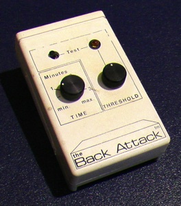
Back Attack, Meath Hospital 1988.
Around 1987-1988 Prof. Davis Coakley, Noirin Sheehan, Jim Malone and I were working on early versions of the OMT apparatus. This activity was based in the clinical engineering workshop in the Meath Hospital (which was a converted corridor!). Others who were around and chipped in were Kieran Maher, Pat Cooney and Brian Murphy. There were a number of other devices in development at MBPE the time including early speech synthesis and automated door locks as I remember.
This project was suggested by Prof. Davis Coakley. Davis had a back problem and noticed that if he stayed predominantly in an upright posture during the day the problem was lessened. He challenged us to develop a sensor and box he could wear that would alert him if he moved into a poor posture position, a kind of posture biofeedback device.
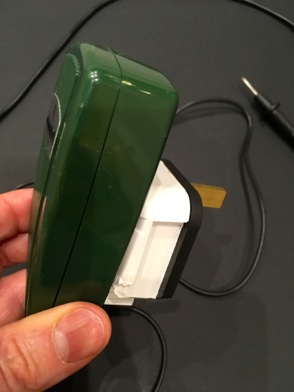
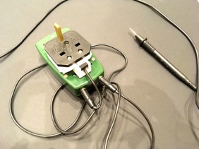
I developed a sensor that was based on a small Hall Effect chip and tiny permanent magnet. Each was embedded into one half of a silicone pencil eraser I had cut in half. These were taped to the lower back of the subject and if they slouched, the magnet would move away from the Hall Effect chip and this would trigger the feedback device which was built into a typical pager clip on box.
Ocular Micro Tremor Devices, 1986 - 2014.
Finder, St James’s Hospital, 2008
DVD Interface, St James’s Hospital, 2003.
Defib Tester where you could vary the impedance
Lung Opening Pressure Simulator
Intra Plural Lung Pressure Measurement
Lung Model incorporating Fluid
Pad Operated Light Switch
EMS
Algometer 2014
Introduction to Maker Culture from Wikipedia: The maker culture is a contemporary culture or subculture representing a technology-based extension of DIY culture. Typical interests enjoyed by the maker culture include engineering-oriented pursuits such as electronics, robotics, 3-D printing, and the use of CNC tools, as well as more traditional activities such as metalworking, woodworking, and traditional arts and crafts. The subculture stresses new and unique applications of technologies, and encourages invention and prototyping. There is a strong focus on using and learning practical skills and applying them creatively.
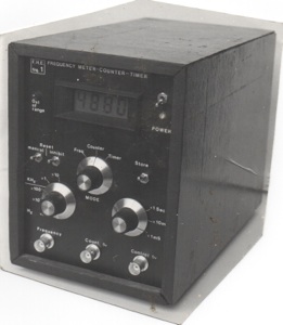
Frequency Meter, Kevin Street College of Technology, 1981.
This frequency meter was designed and built as my final year project in Electrical Engineering in Kevin Street. What my lecturers didn’t know was that it was in fact a digital guitar tuner, these were the days before tuners were readily available. It had an analogue amplifier front end which trashed the input signal to a square wave and then I had discreet digital ICs (before microprocessors) which counted the number of cycles per second. It worked. Wish I had kept it, but resources were scarce in the 80’s and I recycled it into other gadgets.
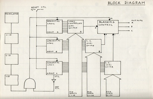
ECG Sequential Switch, Federated Dublin Voluntary Hospitals 1982.
This project was undertaken as part of a six week student placement just after I finished in Kevin Street. It was also my first encounter with the healthcare world. The challenge was to build an analogue multiplexer that could switch ECG electrodes. The wonderful Gerard King (Senior Cardiac Technician in Baggot Street Hospital at the time) had acquired a mat which consisted of 30 ECG electrodes which was intended to be placed on the chest so that you could record 30 V leads instead of the usual 3. So the box I was to design should switch these 30 electrodes, three at a time into the 3 V lead inputs of an analogue ECG machine. I built it and it worked but I never got a picture of it. Again it was all designed and built using discreet IC’s. Below are some scans of the block diagram and circuit diagram. These were the days before PC’s and printers so circuit diagrams had to be drawn by hand. I loved doing this part of any project and soon learned the value of representing technical and logical designs in graphics.
I am pretty sure it was this student project and the associated presentation that brought me to the attention of the F.D.V.H. Medical Engineering team, as I got a job with them about a month later.....and never left !
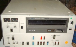
ECG MODEM, Baggot Street Hospital - St James’s Hospital, 1983.
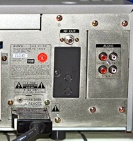
In 1983 the Cardiologists in Baggot Street were doing early interventional cardiology. The angiography images were recorded on big Sony U-matic video tape machines, then the state of the art. The Cardiologists were interested in quantifying the change in ventricle size during the cardiac cycle. The Medical Physicist in St James’s Hospital was Michael O’Connor and he had a system that allowed him to quantify areas on Nuclear Medicine scans that were timed to the heart rate using ECG (MUGA). So Michael figured he could quantify the areas in the recorded angiography but...his software needed a realtime ECG as well as the video to make the software work.
The bit I liked most about the solution was that the U-Matic machines had a compartment on the back panel for plugging in a module that allowed the machine to be controlled by a Sony editing suite. So I designed and built both circuits to fit into these spaces and pick up the power supply from the multi connectors meant to connect to the Sony sync hardware. A very elegant solution if I say so myself. Note the alternative use of the audio channel.
So myself and Charlie O’Neill then Chief Technologist set about trying to solve this problem. What we did was convert the ECG recorded at the time of the angiography in Baggot Street into a frequency (500 Hz) which was modulated by the ECG voltage. This tone was recorded onto one of the U-Matic machines audio tracks. Then on the similar U-matic in St James’s we built a circuit that converter the varying tone back into a 1 volt ECG signal to send to the ECG input of the Nuclear Medicine MUGA system. Worked great.

Magtrak Signal Processor, St James’s Hospital 1984.
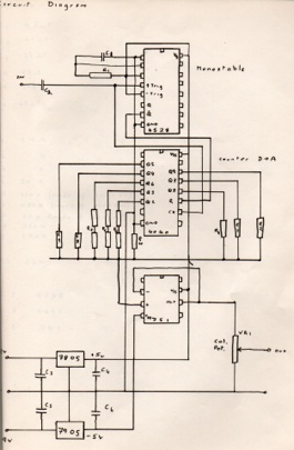
This project was suggested by Dr. Ron Kirkham then an Anaesthetist in St James’s Hospital (when the Theatres were in hospital 7). Ron was also an Engineer and he collaborated with those of us who were forming the Medical Physics and Bioengineering on lots of projects. Ron had an electronic flowmeter called a Magtrak. This gave him an instantaneous readout of gas flow being delivered to the patient during surgery However he asked me to hack the Magtrak to see if I could process the signal to give him an analogue signal that he could plot on a paper recorder to give a volumetric waveform.
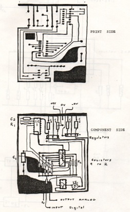
The Magtrak produced a pulse train where the frequency was proportional to flow rate. The circuit I designed worked like this. It counted the pulses and in doing so integrated the instantaneous flow rate into a delivered volume signal. At the end of each delivered breath the flow rate fell to zero. When the circuit detected this zero flow rate it reset the counter. Then I used a resister network to convert the counted number in HEX into an analogue voltage which went to a standard strip recorder. It worked great and went into service in Hospital 7 for many years. Sorry no photos, but it was visually unexciting being literally a black box that sat under the Magtrak. What was exciting was that this was the first time I (and the MPBE Dep.) made a printed circuit board. Still in the days before P.C. and graphics packages, let alone Eagle or DesignSpark and companies who will etch your design. The layouts were hand drawn on acetate. The acetate then laid over copper clad boards with a UV sensitive etch resist layer. Blast with UV. Take off the acetate. Etch in acid A to remove the etch resist layer where the UV hit it. Then etch in acid B to strip off unwanted copper. Finally drill holes for components. See circuit diagram and board lay-outs below.
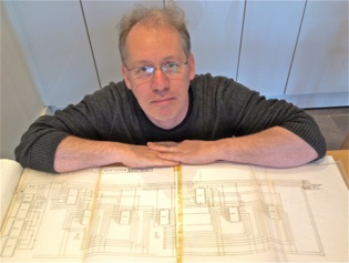
Me 2014 with the original hand drawn circuit diagram from 1982

Gerard King and I from 1982
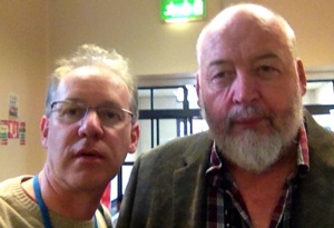
Gerard King and I from 2014
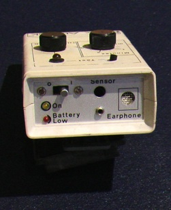
The controls on the pager box allowed the user to set the degree of flex of the back before the alarm would go off. It also allowed for a time period before the alarm would activate. We found 30 seconds was sensible. When it alarmed the device would vibrate to provide haptic feedback or you could use an ear piece to get the feedback.
We built and tested the device and it proved to work but had some design flaws. The sensor was wired back to the pager box, and we didn’t have access to the tech or money to develop a wireless version.
We never did a formal study with this, so we never published it. It was a good idea but had to construct with tech available back in the day.
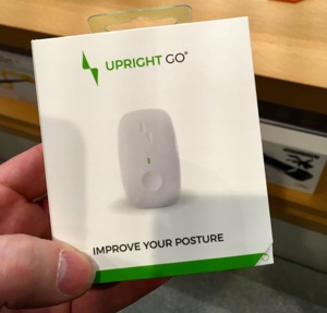
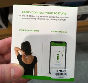
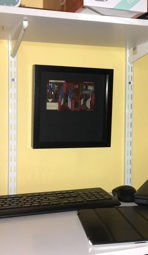
Interestingly, on a recent visit (Nov 2018) to the Apple Store in Chicago I saw modern day version of the back attack for sale. It is sold as an accessory to the iPhone. That seems like a perfect way to implement this idea since everyone is walking around with a powered computer with wireless I/O in their pocket. See the product picture of the commercially available product below.
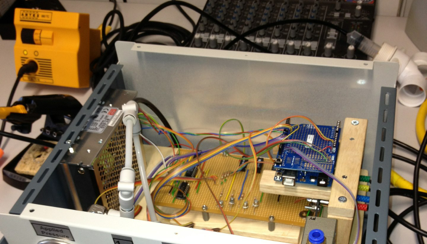
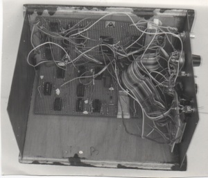
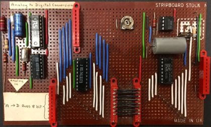
Analogue to Digital - and - Digital to Analogue Converter 1989.
The first intake to the MSc in Physical Sciences in Medicine was in the late 80’s. As part of that first run there was a one week course on Medical Electronics. So I got roped in to teach lots of digital electronic, gates and basic processors etc. One workshop I was asked to set up was a demo to illustrate what digital failures look like! Sound weird now but back in the day engineers were very skilled at finding faults in physiological monitoring circuits due to failure of components by looking at how the analogue waveforms were distorted. So I was tasked with demonstrating how waveforms might be distorted if digital signals paths were failing. Again, a bit weird now but back then large digital systems were implemented using discreet gates and early processors, before the whole software engineering and in chip DSP became the norm.
So I build this eight bit A to D (left hand side of the board) and D to A (right hand side of the board). The top right has a clock which allowed me to vary the sample rate. The two halves of the board are connected by an eight way digital bus so I could scope individual lines and also interrupt particular digital signals to simulate faults.
I would put ECG through this and show the effects of changing the sample rate and loosing different digital lines at different bit depth.
To me there was an art to these circuit design and construction. I found making them very meditative and satisfying. It was important to be that they looked nice and had form. So I kind of think there is a bit of Art going on here. In my home office I have this board framed like a picture and it now functions predominantly an an art object.
A really sensible Electrical Safety Tester for Medical Equipment 2002.
Sometime around 1983, my colleague John Mahady and I spent about ten months checking medical devices in the then Federated Voluntary Dublin Hospitals. This involved performing electrical safety checks on medical equipment using a fantastic tester designed to perform the 30 or so tests that were commonly used at the time. We must have tested >7,000 items in that ten month period. At the end of it, the only electrical safety problems we found were either physical damage which we identified by eye, or a broken earth wire. This started me wondering why we had spent so long testing each device...and why we carried the very heavy tester around.
Jump to 2002. OK this paragraph is for electrical safety nerds! By 2002 all equipment in use was built to comply with IEC601. Good design, good materials and designed to fail safe. I argued that unless an item suffered sever physical damage its leakage currents were not going degrade over time. So, once checked at commissioning and after a maintenance service, there was little need for testing the leakage currents. Similarly with the insulation resistance. So for Class I items the only thing worth checking was the earth continuity, because a faulty protective earth connection could be a hidden fault. If there was a live or neutral fault the device would fail safe. So routine electrical safety of Class I items reduced down to checking the earth continuity (pity I hadn’t figured that out in 1983!).
To test the earth continuity of a medical device using commercially available electrical safety testers requires you to plug the item under test into a special tester. So this is impossible to do for most items which, if they are doing what they should do that is working for a patient, they will be connected to the mains outlet and that connection can not be interrupted.
So I built a simple earth continuity tester that plugs into an available 13 amp socket in the clinical environment in which the medical equipment is used. It is an adapted RS Continuity Tester (part no 421-002). One side of the test circuit is attached to the earth pin of the 13 amp plug-top glued onto the tester. When inserted into a 13 amp socket outlet it makes contact with the protective earth conductor behind the wall. (N.B. the live and neutral pins have been removed so there is no possibility of accidentally coming in contact with the current carrying wires). A probe is connected to the other input of the tester. In use this probe is touched off the exposed metal parts of any medical equipment being surveyed. If the continuity if below a few ohms a buzzer sounds. This can be used to check there is a protective earth connection on medical equipment in use on a patient safely and quickly.
Great for routine checking and provided its use is augmented with comprehensive testing in the workshop on commissioning and after repair, and an end-user campaign to teach and raise awareness of electrical safety, it is all that is needed to supplement a visual inspection of medical equipment to perform routine electrical safety checking in my humble opinion.
Electrical Safety Training Video for Hospital Staff.
In 2012 the Medical Device Vigilance Group in St James’s identified a need to raise awareness of electrical safety issues associated with the use of medical equipment in the hospital. To support this I made the training video below which is used as training material in the St James’s Intranet.
It is designed for what Doris Lessing would call “the common reader’ that is a member of staff familiar with the use and application of medical equipment and usual clinical practice but who is not schooled in engineering theory. So technical folks should forgive the simplification of the technical terms.
The intention is to make staff aware of the role they can play by adopting good practice and reporting faults when they see them. Click the screen below to see the video. It takes a few seconds to start, to give you time to turn on your speakers.